
2708 / 2704 EPROM reader / programmer
The restoration of computers like our SAGA FOX LS-1000, containing an EPROM 2708, gave us the necessity of reading, and so storing, the content of this kind of EPROM, before their age can become a problem, wiping out the data stored in them.
Common EPROM programmers like the one we have at our Museum can read/write at least 2716, but not the old 2708. Professional tools that can do this task are really expensive.
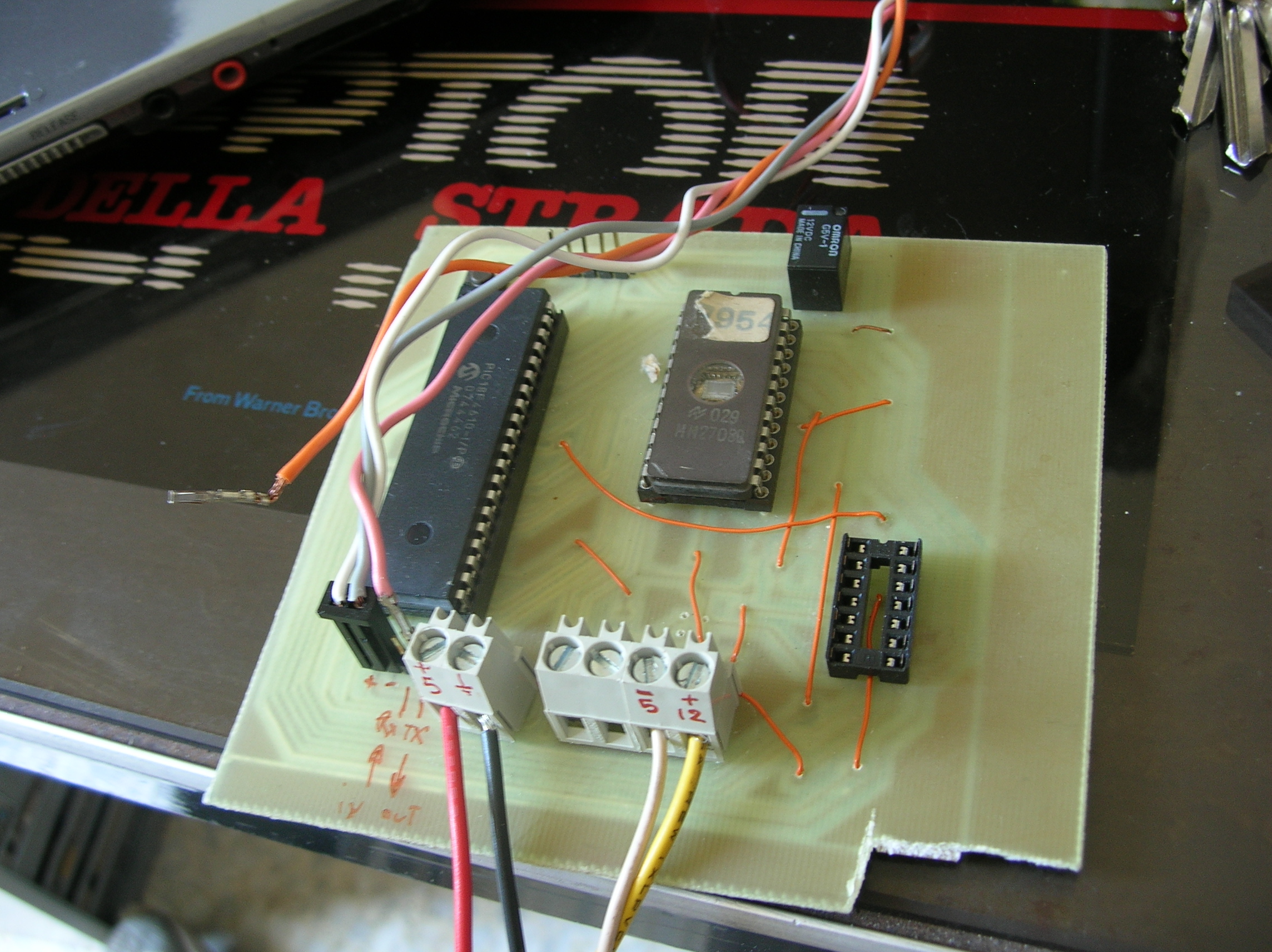
So we decided to create our own 2708 EPROM reader, using a PIC and an external power supply.
2708

Per leggere la EPROM 2708 bisogna alimentarla con -5V al pin VBB (21), +12 V al pin VDD (19), +5V al pin VCC (24) e ponendo il pin VSS (12) a massa. Poi si deve collegare il pin Not Chip Select (20) ed il pin di programmazione (18) a massa. A questo punto basta scrivere nel bus di indizzamento (A0…A9) l’indirizzo di memoria da leggere, aspettare che il segnale di uscita si assesti (secondo il datasheet al massimo 450 ns) e leggere nel bus dati (Q0….Q7) il dato letto.
Circuit
To read a 2708 eprom we need 10 output for the address bus, and 8 input for the data bus: a total of 18 digital I/O. Moreover, we need a way to transmit data to a PC, so we need other two pin for a serial port.
We choosed a 40 pin, 8 bit microcontroller, the pic18f4610. The digital port of this pic are divided into 8 pin digital I/O groups, and their value can be handled as an 8 bit integer.
The 2708 data bus is 8 bit, so we can directly connect the bus data to one port of the PIC. Moreover, the address bus is 10 bit, so we need two other pin; we choosed to connect the 8 less significative bit of the address data to the B port of the pic, and the remaining 2 pin to two other pin in the PIC, using them as digital signals (C0 and A1)
Software
The software suite is divided in two pieces: the firmware for the PIC and a Python program to read the EPROM data and send it to a PC. In the firmware, reading a location in the EPROM is very simple: we write the addrress into the address bus, writing the first 8 bit into port B and the remaining two bit in the digital port C0 and A1 (connectedo to A8 and A9 in the EPROM), wait the assestment time for the output to become stable, and read the data on the data bus:
/* Read a byte from 2708 eprom

@param address: The address to read

@return The value read

*/

int read_eprom(long int address)

{

    ADDRESS = address;

    A8 = (address & 0x0100) >> 8;

    A9 = (address & 0x0200) >> 9;

    /* Wait. Address to Output Delay Time */

    delay10tcy(10);

    return DATA;

}
The PIC firmware read the content of every EPROM location (calling read_eprom function with any number between 0 and 1023) and send the content to the serial port.
Data is trasmitted to the serial port as an ASCII character, representing the hexadecimal value that has been read. Every byte is separated by a space character. Every 16 bytes, we send a CR (\r) and a LF (\n). Every time the reading restart from the beginning, we transmit the string ‘##\r\n’.
Our Python program read the EPROM content and send it to the serial port for 5 times; those reading are compared and, if they are the same, it save the content on a file in binary format (.BIN), that so will contain our EPROM data dumped 😉
Serial port to be used on the PC, speed and connection parameters, the number of readings and the file name to save the dump can be changed editing the header of the Python code.
2704
2704 EPROM are very similar to 2708; the only difference is their size (512 bytes instead of 1024). Pinout is the same but the address bus, that is 9 bit instead of 10. So, the pin 22 , that in the 2708 is the 9th address line, in the 2704 is a ground. For this reason, it’s simple to modify the PIC firmware to read this kind of EPROM. We must simply set the A1 digital port (connected to pin 22 of the EPROM) to zero, and read only the values between 0 and 511.
Programming
To burn the 2708 EPROM we need to power them as follow: -5V to the VBB pin (21), +12 V to the VDD (19) and the Not Chip Select pin (20), +5V to the VCC pin (24) and set the VSS pin (12) to ground; we also need to initially put the programming pin (18) to ground. At this point we have to simply write on the address bus (A0…A9) the address of the location to program, in the data bus (Q0….Q7) the data to be written, and set the programming pin (18) to +26 V to program it. We need to wait the correct time for the data to be burned (about 1 ms according to the datasheet) and put back to ground the programming pin (18).
We are in the process of creating the burning part needed in our circuit board, the PIC software and the corrispondent burning utility in Python. This is not a difficul task, but now we don’t need it in a hurry because, in case of necessity, we can simply change a 2704 or a 2708 with a 2716 or a 2732, just programming their first 512 or 1024 bytes, because those EPROM are pin to pin compatible.
Download:
PCB board layout and circuit schematics
The entire project was created by Andrea “Mancausoft” Milazzo.
Please write us about any error, missing part or comments!